

\$ P = VI = 24 \times 0.012 = 0.288\ \text W \$ so I would use a 0.5 W resistor for both the interface and additional load. If you wanted you could add an LED in series with each resistor. That will draw an extra 12 mA and satisfy the output requirement without compromising the stepper input recommendation. They would probably be fine at > 20 mA but without a datasheet for the opto-isolators it would be taking a chance.Ĭould a voltage divider placed between the driver and controller handle this problem? Maintain a voltage of 5 V at driver input pin and draw 21 mA current from the controller.Ī simpler solution would be to add a second 2k resistor to ground from each output. The stepper driver seems to be looking for about 10 mA per input for its opto-isolator LEDs. This will drop the current consumption below the 21 mA requirment of the controller.Ĭorrect.
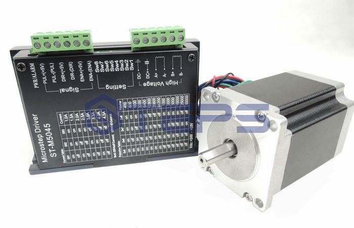
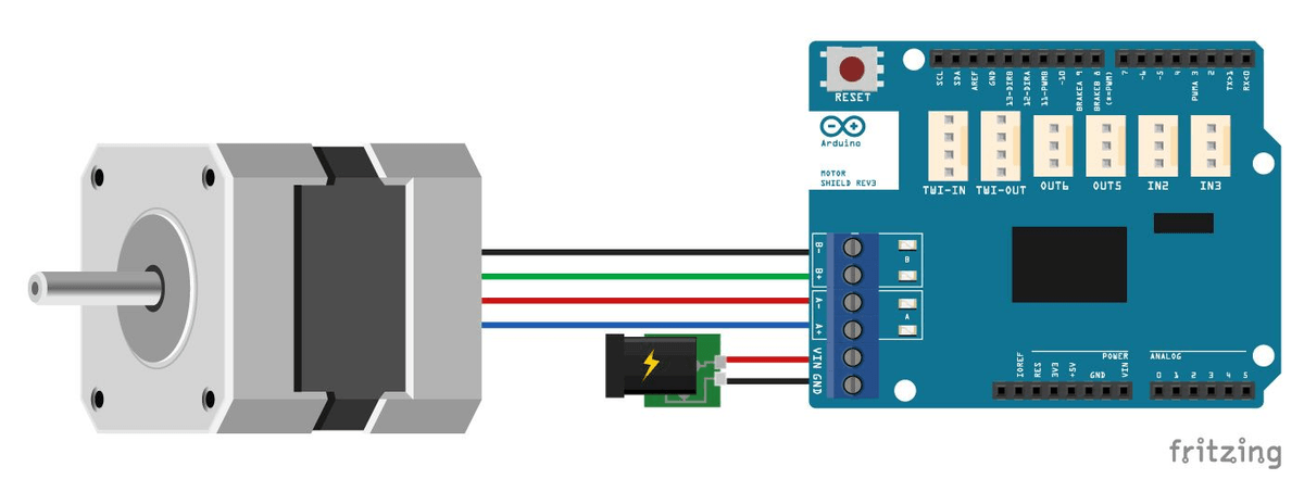
The ST-M5045 stepper driver data sheet says in order to use 24 volts as input a 2k resistor must be placed at the input. Adjust the trimmer POT of the voltage regulator until it shows about 5vdc with the stepper motor running, 0.75 n/min you should be pulling about 0.24mA. Since these are almost certainly opto-isolated FET outputs I would expect them to work down to a few volts but the table makes it look as though they are only rated for close to 24 V DC. and the output voltage of the pins are 24V. I have never seen a minimum current specification like that before. There is a minimum current requirement in order to use the FET pins on the Micrologix controller of 21 mA.